STAR WARS: Episode VII – The Force Awakens LPA NN-14 Blaster
The Rey gun!
Because, apparently, I’m incapable of being reasonable, I decided for my second trick I’d do the LPA NN-14 that Han gives Rey on Takodana in The Force Awakens. Not in foam or resin, but in metal.

“I think I can handle myself.” “I know you do, that’s why I’m giving it to you!”
It caught my eye, because despite being objectively fairly unbalanced, lumpy and ugly, it has some individually beautiful design elements, as well generally appearing to be an homage to Original Trilogy lightsabers. It looks to be the only blaster we’ve seen so far manufactured by LPA, which makes sense because it’s heavily divergent from the general design lines common to most of the blasters we see in either Old Republic/Pre-Empire or Empire/First Order settings.
On top of this, it’s relatively simple to machine manually due to its mostly 30’s machine-age aesthetic. This is very appealing to a guy who hasn’t yet built any CNC technology! Similarly important for me right now is that every part of it fits into a 4? square, which is all the space that my lathe milling attachment gives me- and even then, the extremes are iffy because the dovetail ways and gib on the thing don’t have a lot of grip on each other and can rack under pressure from the cutter. Sometimes it’s better to flip parts around near the end of its travel.
This isn’t going to be a completely exhaustive build log by any means; that’ll come if I can find the time when I build version 2, hopefully later this year. But I will touch on the highlights, with plenty of pics to break it up. Don’t be fooled, this is still a seriously substantial write-up, should probably grab a beverage of some sort… But there’s a lot more to it than this. Ok, let’s get started.
Design and Blueprinting
First up, modelling. I looked at a handful of 3D printable models, but none of them really came close to the accuracy I was looking for. So the only way was to try and model it myself. I’d never tried to over-model anything before, but I gathered a ton of reference, as much as possible from every angle. As you can see above, the actual movie screengrabs have the blaster quite small in the frame, and aren’t much use. Most of what I was looking at were random photos of exhibit models (re-machined for exhibitions, not screen-used, but dimensionally accurate, presumably; only potentially differing in details) and Visual Dictionary images.
I’ve since deleted the virtual cameras that actually held these views, but the general gist was this:

Visual Dictionary based image as the background, actual model in the foreground.
The trick to overmodelling like this is really fairly simple. Knowing that what you’re looking at is distorted in some way, whether it was shot with a real camera and lens or a virtual one, you have to try to reverse that distortion to get an accurate representation of the object’s proportions.
Right in the center of the image, you can generally trust the proportions of things. Out toward the edges, you have to try to reverse the barrel distortion (it’s almost always barrel, rarely is anything shot with a lens long enough to cause pincushion distortion). If you’re axis-aligned and modelling in orthographic view, you have to both “imagine” where the center of the feature is (and if it’s a part offset from the primary plane, good luck), which is easier with cylindrical cross sections than rectangles, and gauge exactly how much distortion is shortening the apparent width of the feature you’re modelling against, which is mostly educated guesswork.
A better way is to add cameras on every axis, and with the help of a couple of handy visible cross-sections, ideally known cylinders, adjust the focal length and positioning until the virtual camera distorts the 3D shape into exactly the same shape as the image feature at the same point in the frame; you then know that you can freely model away against the features in the image without worrying about foreshortening and mis-proportioning; essentially you’re calibrating your virtual cameras.
Once that was done, it was a case of heading over to Fusion 360 and remodelling all the separate parts parametrically, based on the measurements of my vertex model at the scaling I decided on. Fusion is generally pretty friendly to work with (and free!) so this wasn’t too bad.

Fusion 360
Fusion generates blueprints from models automatically based on a few parameters. You then have to add all the projections and measurements, but this is pretty quick and easy.
Grips
This was really pretty straightforward. Since I needed the 11-line grips of the Mauser M719 Schnellfeuer (ie. the machine-pistol version) rather than the 35 lines of the standard 7.63mm C96 or the “red 9” grips of the 9mm Parabellum version, I just bought an Umarex Legends M712 CO2 blowback air pistol, for which I specifically saw reviews comparing its accuracy favourably side-by-side with live original M712s.

Umarex Legends M712 Schnellfeuer CO2 blowback.
Why buy a $110 (at the time, I saw it recently for $75) air pistol that I didn’t need just for the grips? Because I’d waste a hell of a lot more than $110 in time trying to recreate that exact organic shape in Monster Clay- in perfect symmetrical duplicate, no less- so I made the executive decision to trade money for time.
Taking the grips off was easy enough, and I used it to test my 3D model/CAD design scaling against (since I’d picked a length that looked right- I forget now, around 32cm- from the several numbers I’d seen mentioned online), and it turned out to be absolutely spot on, so no computer rework required!

Testing blueprint scale with the real thing.
Since there are two counterbored mounting holes in the NN-14 grips, rather than the single central hole in the M712, I had to fill in the hole with Monster Clay before I could start moulding it.

Filled mounting holes
That took a little while to exactly match the curvature and groove geometry, but worth it since it would make life much simpler down the road.
Then it was just a case of moulding the grips so I could recast them in solid Smooth-On Onyx. I did a simple open-top brush-on mold since I had some Rebound 25 lying around doing nothing.

Rebound 25 mould with 3M polyester fiberglass mould jacket.
They came out fairly cleanly, just a little sanding and the new mounting holes to drill!

Raw Onyx casts
Barrel
On to the machining. It gets a little more straightforward here.
First off I did the barrel tip from 304 stainless round stock, turning in the shoulder that allows it to sit inside the main tube and drilling the bore, then using the shoulder to hold it in the chuck while I did the sequence of faces and bevels to take it to final shape.

Turning the barrel tip
The side holes were drilled and tapped later after the tube was finished.

Barrel tip
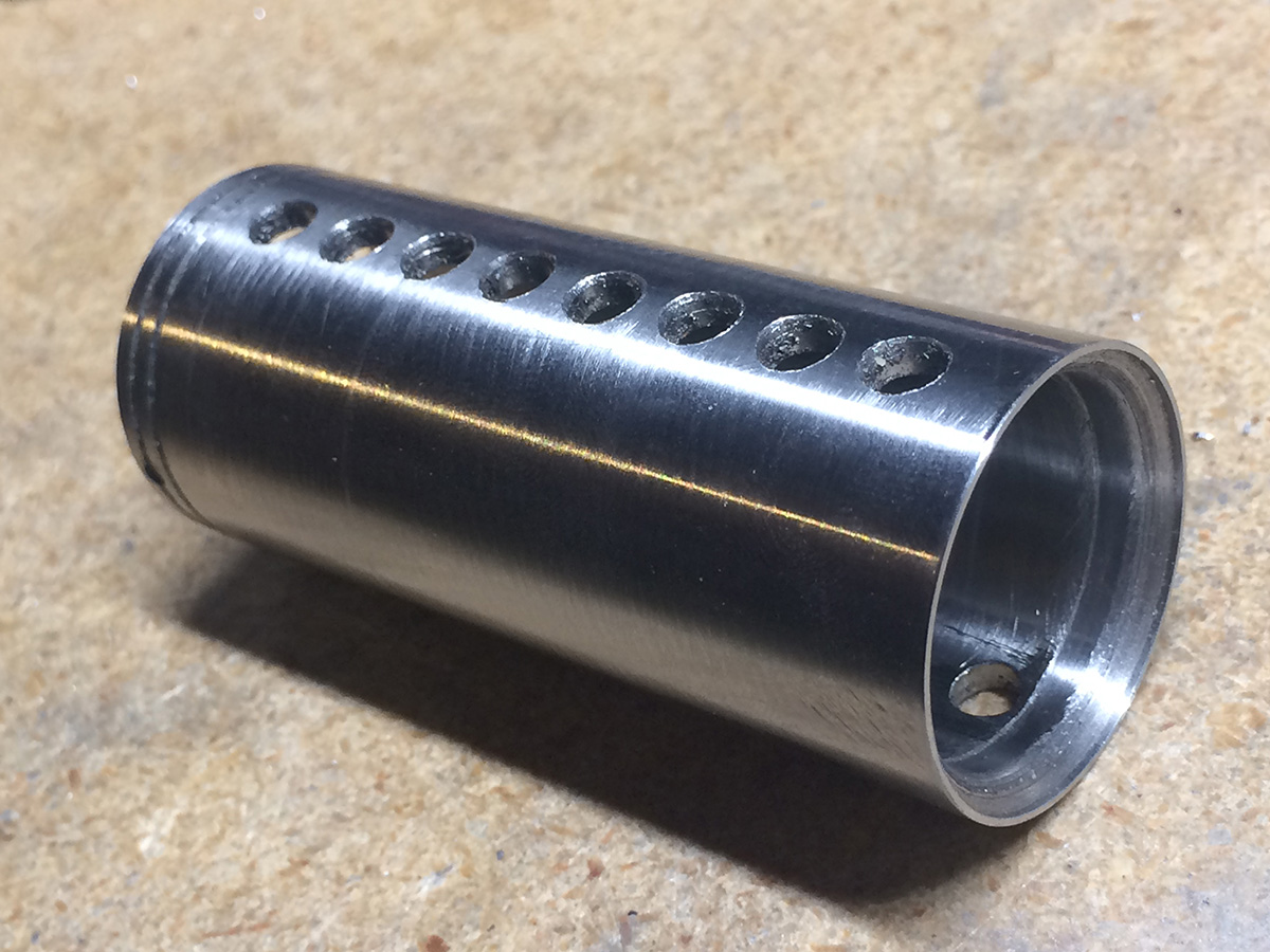
The barrel was bored and turned to inner and outer diameters respectively, grooved the front pattern, and then the vent hole pattern drilled.

Drilling the barrel vents
The bevelled shoulder in the back was added later after I had the mounting flange made so I could keep testing it.
Finally I needed a method of actually connecting this tube assembly to the main body, so I made a mounting flange from aluminum (WAY easier to work with than stainless steel).

Rear barrel mounting flange
I was trying to optimise for ease of fit and surface area for gluing, whilst not going so far forward that I started running into the vent holes. If I’d had a TIG welder, I’d have turned it out of more stainless and left a bevel gap in the rear so that I could carefully seam it together, but as it is, it had to be epoxied. The idea here was that the whole barrel could be bolted removably to the main body with an M8 socket cap screw.

Barrel and barrel flange

Chassis and barrel flange
Finally, I heat-discoloured the tip while the whole thing was screwed together. The bottom was supported on an aluminum block in water so that it wouldn’t be touched, as well as act as a chill block most of the way up to the tip whilst allowing for a natural-looking taper off to the colouration.

Stainless for true heat-discoloration rather than painted aluminum.
The blue oxide colour I was aiming at was around 550-600F, though I was sorely tempted to leave it at the beautiful gold of 400-450F’s mid-straw temper!
Chassis
I wanted to build the whole thing around two chassis bars that would simultaneously hold the two side plates at the right width, connect to the half rounds, hold the grip frame, and be centered on the front protruding features, so that the whole thing could be reasonably straightforward to assemble and disassemble as necessary.
These were made from 6061-T6511 aluminum stock, like all the other aluminum parts of this build. Just a simple square bar with a slot in the back to accept the front “plug” of the grip frame, and turned/bored/tapped areas in the front to accept the front pieces, and then drilled and tapped on the sides accordingly.

Chassis bars with other pieces in progress.
Trigger
The trigger I decided to also made from 304 stainless bar, simply because it would feel heavier and more “real” than an aluminum one.
While the rear, angular geometry of the trigger was easy enough to layout, the front with its multiple curve radii proved quite difficult. So I made a template from Monster Clay directly from a 1:1 print of the blueprints, and sprayed over it then scribed on top of that onto the sheet metal to follow.

Trigger template
After cutting, a little extra sculpting and filing to final shape, it was ready to go.

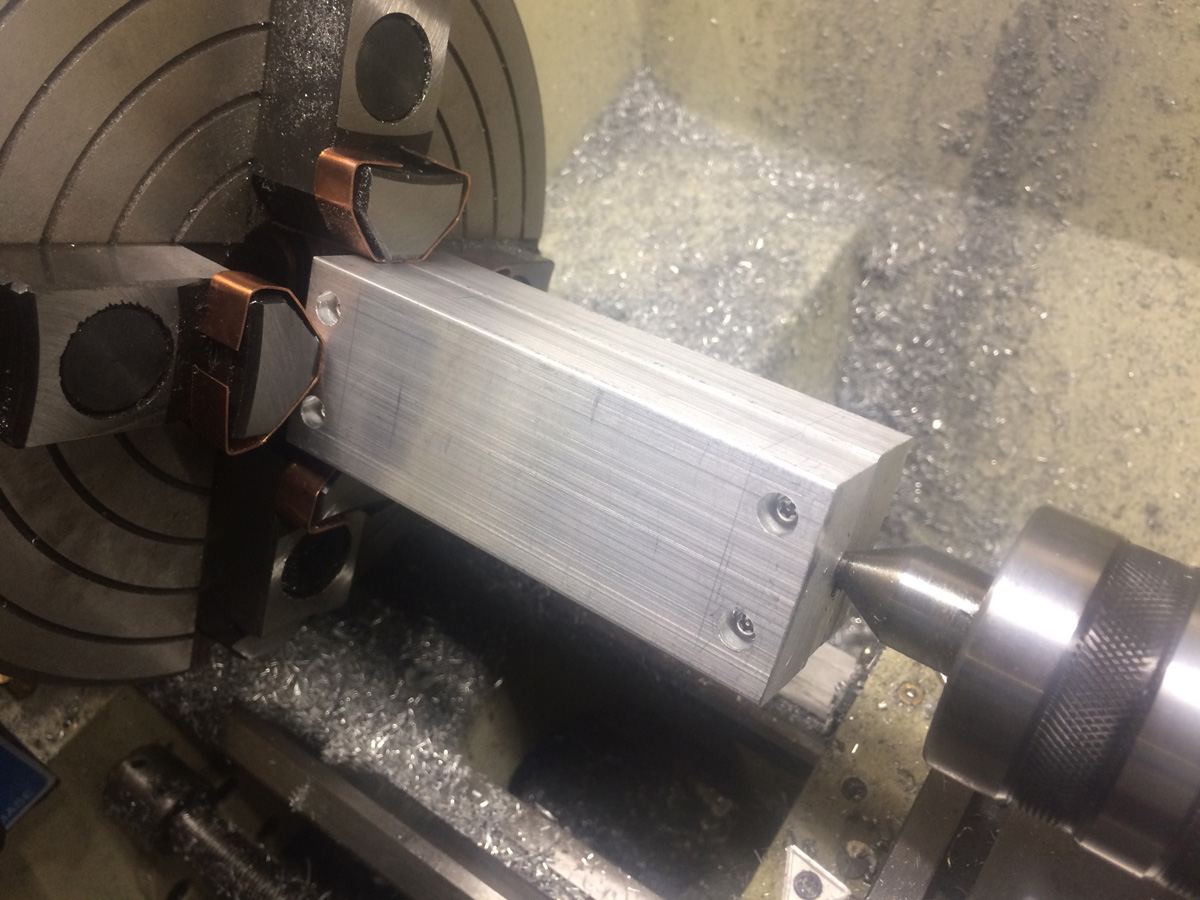
Body: Half Rounds
Now, the most visually arresting part other than the barrel! These started their lives as aluminum rectangular bar stock, which was cut to approximate length on the miter saw, then one side faced down with the insert dovetail cutter I use as a face mill, before a couple of hours of, essentially, lapping. I wanted the surfaces as smooth and flat as possible so that once they were put together, it would be easier to align the central axis with the z axis of the lathe- even just 5 thousandths of an inch or so out would be quite noticable on the final product in terms of alignment and angles.
Once they were flattened, I milled a pocket right in the center of each one so that I could just use the chassis bars as alignment pins- since they’re what would be doing the alignment in the finished pieces anyway.

Chassis bar pocket in lapped bar stock
So, I had to do that four times (yeah, that was a lot of lapping) to get the two pairs- they had to be done in pairs simply due to practicality- trying to turn a single unit would be ridiculous, and of course top and bottom half founds are different. I didn’t want to just turn a single solid one and then cut it in half, because a) even if I did somehow slice it perfectly, I’d still be losing about 15 thou per piece to saw kerf, and b) it would be a lot harder to mill a perfect pocket onto an already-rounded part.
So, once I could put them together, aligned by the chassic bars, I drilled blind holes, counterbored and tapped them, and they looked a little something like this:
Half round stock ready to turn.
In future, I’d mill down all four sides to make it easier to align on the lathe; I think when I measured them at the end, they were 1-2 thou out, but that’s only really noticable super close-up.
After turning them down, it looks like this:

Turned half-rounds
…And then after unscrewing, they look rather nice!

Half-rounds ready to trim off
This particular section was where I once again re-learned the value of “penny wise, pound foolish” when it comes to materials. Even when you’re on a budget, don’t skimp on oversizing raw stock for workholding… You’ll end up wasting twice as much material for your troubles.
Body: Sides
Made from 1/4? plate stock, these were a fairly simple case of milling down all sides, and lapping to the level of finished that I wanted.

Lapped side plate against unfinished plate
Then just a case of slotting them with a slitting saw, though in retrospect without a proper saw arbor (mine broke, and my improvisation was somewhat substandard) I should probably have gone with broaching using the same single point grooving tool as I used for the barrel and half-rounds.
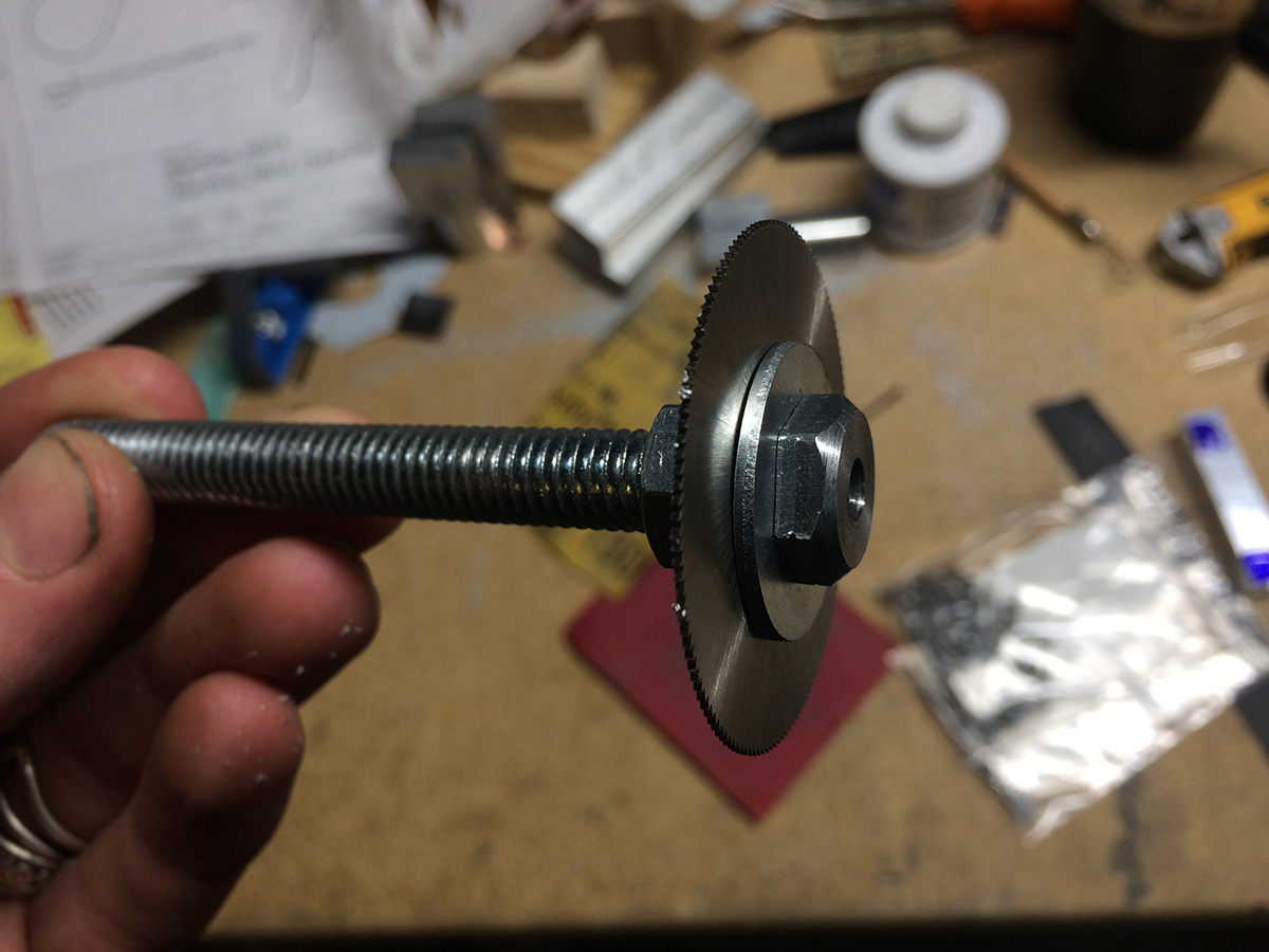
Yeah, that’s a 3/8? bolt. So ZERO runout, right?!
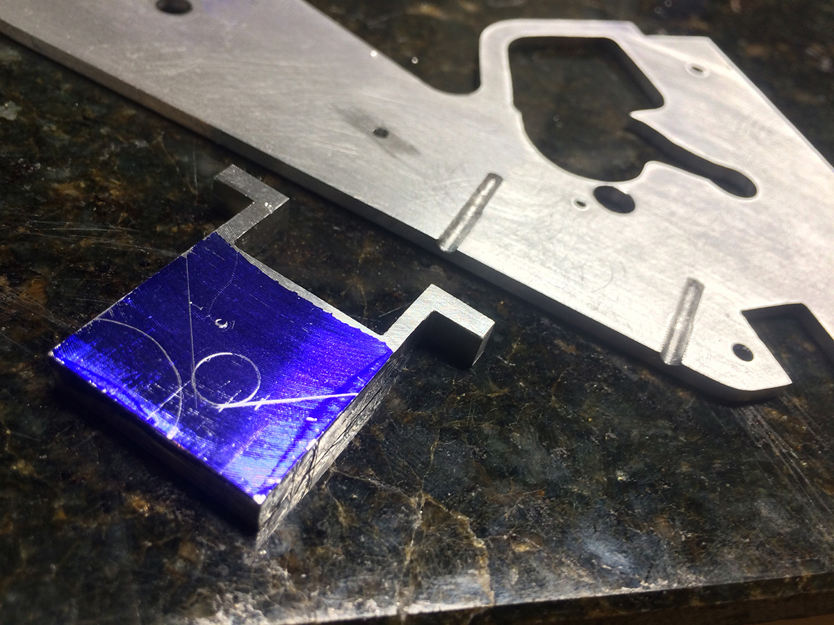
Once that was done, I needed to put the square in. I had a system of decreasing circles all figured out into the corners, but some nasty chatter decided that wasn’t actually going to happen, and I had to improvise a little bit.
The black was made with more Onyx resin, held in with a scuffed up base and some through-holes, countersunk on the other side (so it can’t pull back through) and taped over with aluminum tape (so I could actually pour the resin).

Pouring the Onyx squares
Final results aren’t super great, but I’m not so unhappy; it looks pretty grungy and “lived-in”.

Finished side plates with Onyx inserts
Grip Frame
This was a slow part, no way around it. If I had a little CNC gantry router, I could have made it super easily with that, but I’m not a fan of them, so I don’t!

Templated grip frame
This was just templated, cut, filed, the works. Not really all that much to say, it was just a lot of hard work. I powered through it by imagining how much more work Tom Lipton’s handmade Baby Wilton took!

Lots and lots of hand-filing.
All hand-work, no machining. A little bit of power tools here and there where I thought I could get away with it. Took a few days to really get to where I wanted it.

Much closer to completion
Safety Mechanism
This was, at last, the first mini-mechanism I’d done that actually worked. I think the previous ones (as ingenious as they were, if I do say so myself) were scuttled by being made out of plastic. I carefully designed this one around the features that were actually present, so that it would be a simple addition, as you’ll see.
First I started with the top plate, which was fairly simple.

Safety top plate
I slotted that, then got to work on the actual toggle. This required not only knurling, but what appeared to be two different pitches of knurling to make a parallelogram knurl rather than a diamond knurl. I had to make a custom tool.

Custom knurling tool
Dubious welds and definitely not straight wheels, but it did the job! After finishing the toggle off, I had something pretty decent looking.

External parts of the safety
Pretty sure she doesn’t even actually move anything there, just pretends to fiddle with it. Rob 1 : ILM 0!
Next there was a lot of, well, ridiculousness, to get the internal housing to work.

Drilling and tapping the grip frame
The body and frame.

No margin for error on this bit, but I got there
Then there were even more calculations, some more drilling and tapping, and I had something distinctly resembling a mechanism!

Finished safety mechanism
Miscellaneous Parts and Assembly
I chopped up the grip some more and wound a spring to get that whole back end functional:

Mechanisms
Made up the front and rear body plates, shimmed the side plates to just where I wanted them, that kind of thing.

Front plate (movie version… I think)
Then this thing was done! In record time, to boot, and only one semi-major error (the barrel is actually 2.5mm too short… Again, v.2.0 fix!) that I’m sure no one probably noticed until I just mentioned it.

All completed parts
Once it was assembled, I took some pretty pictures!

Final piece 1

Final piece 2
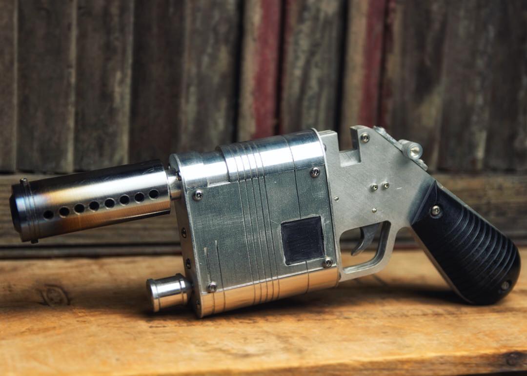
Final piece 3
Not sure why they’re all from basically the same angle, but I guess I like it. I’ll be weathering it at some point, and then doing a “proper” beauty shoot, but you know how life likes to get in the way of that stuff.
All for now!
~Rob